这是本文档旧的修订版!
ESP32-C3Mini
Introduction
ESP32C3SuperMini is an IoT mini development board based on the Espressif ESP32-C3 WiFi/Bluetooth dual-mode chip. ESP32-C3 is a 32-bit RISC-V CPU, including FPU (Floating Point Unit), which can perform 32-bit single-precision operations and has powerful computing capabilities. It has excellent RF performance and supports IEEE 802.11 b/g/n WiFi and Bluetooth 5 (LE) protocols. The board comes with an external antenna to enhance signal strength for wireless applications. It also has a small form factor combined with a single-sided surface mount design. It is equipped with rich interfaces, with 11 digital I/Os that can be used as PWM pins and 4 analog I/Os that can be used as ADC pins. It supports four serial interfaces including UART, I2C and SPI. Also on the board is a small reset button and a bootloader mode button.Based on the above features, ESP32C3SuperMini is positioned as a high-performance, low-power, and cost-effective IoT mini development board, suitable for low-power IoT applications and wireless wearable applications.
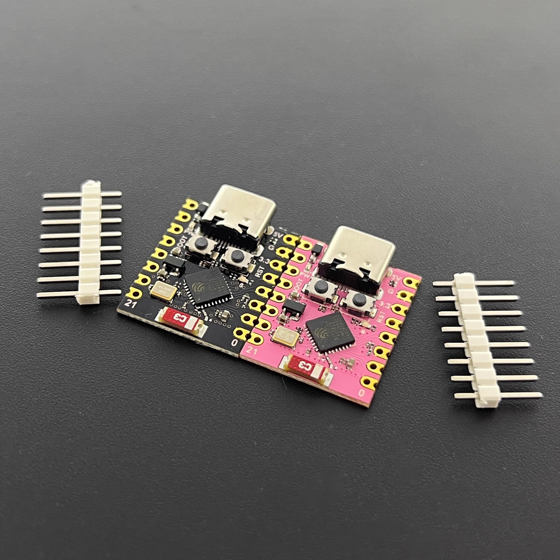 ESP32C3-SuperMini
Hardware description
Product parameters
- Powerful CPU: ESP32-C3, 32-bit RISC-V single-core processor running at up to 160 MHzWiFi: 802.11b/g/n protocol, 2.4GhHz, support Station mode, SoftAP mode, SoftAP+Station mode, mixed modeBluetooth: Bluetooth 5.0Ultra-low power consumption: deep sleep power consumption is about 43μAAbundant board resources: 400KB SRAM, 384KB ROM built-in 4Mflash.Chip model: ESP32C3FN4Ultra-Small Size: As small as your thumb (22.52x18mm) Classic form factor for wearables and small projectsRobust Security Features: Cryptographic hardware accelerators supporting AES-128/256, hashing, RSA, HMAC, digital signatures and secure bootRich interfaces: 1xI2C, 1xSPI, 2xUART, 11xGPIO(PWM), 4xADCSingle-sided component, surface mount designOnboard LED blue light: GPIO8 pin
Pin diagram
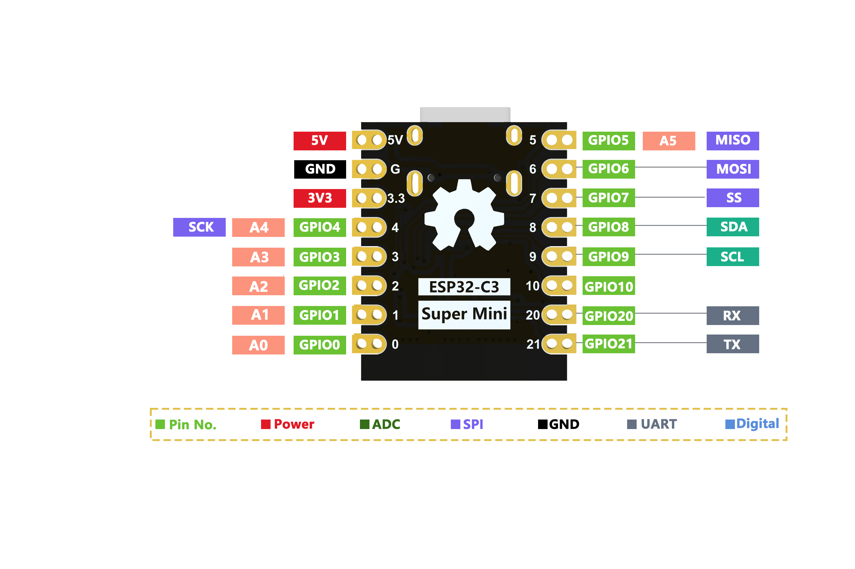 Ardunino ESP32C3 Dev Module 引脚映射
# 尺寸图
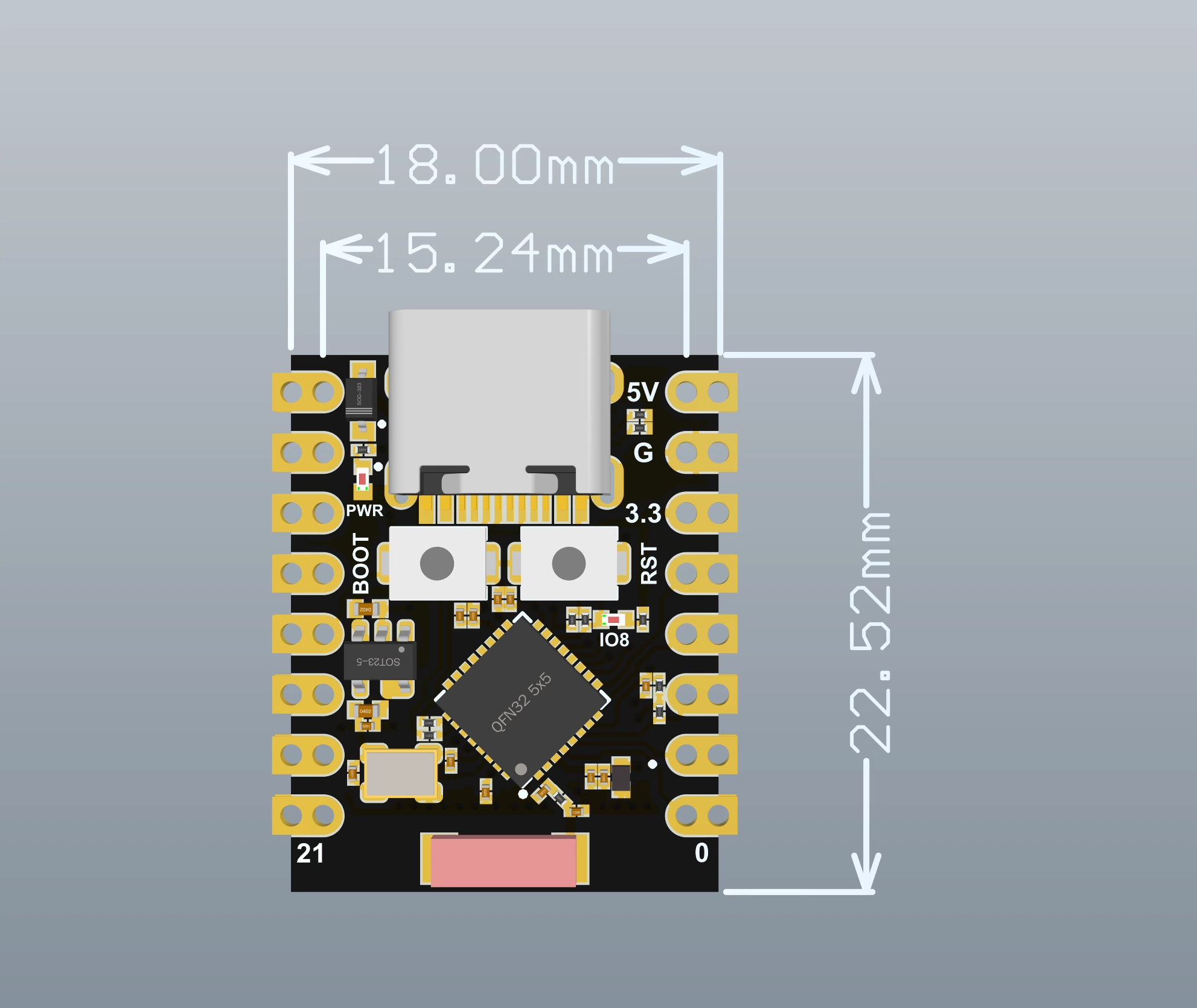 尺寸图
尺寸图
# 原理图
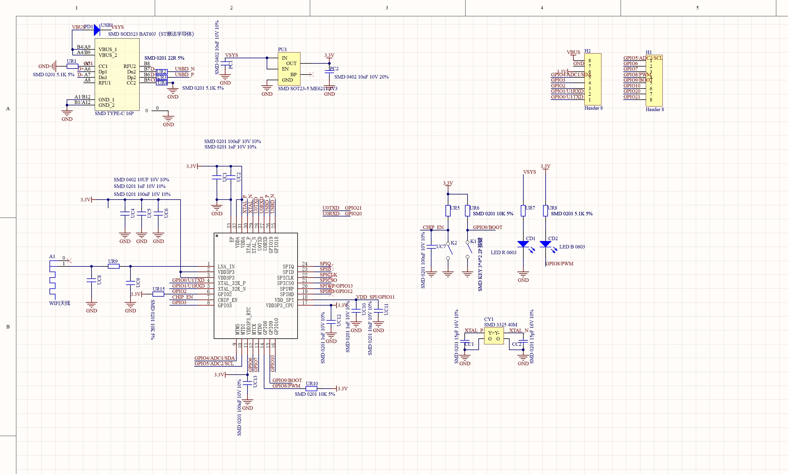 原理图
原理图
# 外接电源
如果需要外部供电只需将外部电源+级接入5V的位置,GND接负极。(支持3.3~6V电源)。切记连接外部电源的时候,无法接入USB,USB和外部供电只能选择一个。
注意
焊接时请注意不要使正负极短路,烧坏电池和设备。
# WIFI天线
如果想使用外置天线,可以按照一下图片外接外置天线。

# 入门
# 硬件设置
您需要准备以下内容:
1 个ESP32C3SuperMini
1 台电脑
1 根 USB Type-C数据线
提示
有些USB线只能供电,不能传输数据。如果您没有 USB 线或者不知道您的 USB 线是否可以传输数据,可以购买Type-c数据线open in new window
- 步骤 1.通过USB Type-C数据线将ESP32C3SuperMini连接到计算机

# 软件设置
- 步骤1.根据您的操作系统下载并安装最新版本的Arduino IDE
{{https://www.nologo.tech/assets/img/arduino/other/ArduinoIDE.png?nolink&}}open in new window
如果下载缓慢可以在国内Arduino社区下载ArduinoIDE下载地址open in new window
步骤 2.启动 Arduino 应用程序
步骤 3.将 ESP32 板包添加到 Arduino IDE
导航到File > Preferences ,然后使用以下 url 填写“Additional Boards Manager URL” :
https://raw.githubusercontent.com/espressif/arduino-esp32/gh-pages/package_esp32_index.json

导航到Tools > Board > Boards Manager… ,在搜索框中输入关键字“ esp32 ”,选择最新版本的esp32并安装它。

导航到工具 > 开发板 > ESP32 Arduino并选择“ ESP32C3 Dev Module ”。板的列表有点长,你需要滚动到底部才能到达它。

导航到“工具”>“端口”,然后选择所连接的 ESP32C3SuperMini 的串口名称。这可能是 COM3 或更高版本(COM1和COM2通常保留用于硬件串行端口)。
# 闪烁的LED
步骤1.将以下代码复制到Arduino IDE
''// define led according to pin diagram
int led = 8;

void setup() {
  // initialize digital pin led as an output
  pinMode(led, OUTPUT);
}

void loop() {
  digitalWrite(led, HIGH);   // turn the LED on
  delay(1000);   // wait for a second
  digitalWrite(led, LOW);    // turn the LED off
  delay(1000);               // wait for a second
}

''
上传后,您将看到板子上的LED 闪烁,每次闪烁之间有 1 秒的延迟。
评论
Can you send me the documentation of these hardware? ESP32-2424S012C-I
Hi! In this topic we share experience about voltage stabilizers from the manufacturer «Energotekh». And also about Infinity series — where to buy: https://ford-talks.appbb.ru/viewtopic.php?p=767#p767
I used to be recommended this website by way of my cousin. I'm no longer certain whether this put up is written by him as no one else realize such specified approximately my trouble. You are amazing! Thank you! xnxx
My site - web page, <a href=“https://my.xnxxtubexxx.cc/”>xnxxtubexxx.cc</a>,
I used to be recommended this website by way of my cousin. I'm no longer certain whether this put up is written by him as no one else realize such specified approximately my trouble. You are amazing! Thank you! xnxx