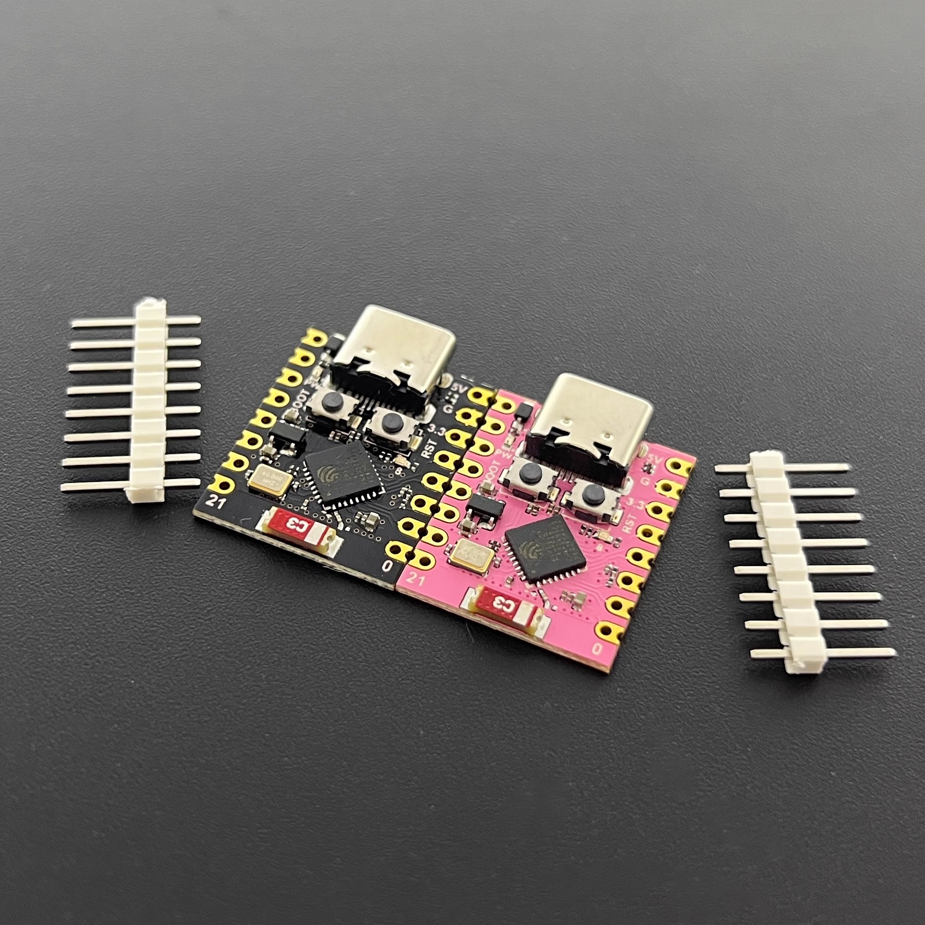
ESP32-C3Mini
Introduction
ESP32C3SuperMini is an IoT mini development board based on the Espressif ESP32-C3 WiFi/Bluetooth dual-mode chip. ESP32-C3 is a 32-bit RISC-V CPU, including FPU (Floating Point Unit), which can perform 32-bit single-precision operations and has powerful computing capabilities. It has excellent RF performance and supports IEEE 802.11 b/g/n WiFi and Bluetooth 5 (LE) protocols. The board comes with an external antenna to enhance signal strength for wireless applications. It also has a small form factor combined with a single-sided surface mount design. It is equipped with rich interfaces, with 11 digital I/Os that can be used as PWM pins and 4 analog I/Os that can be used as ADC pins. It supports four serial interfaces including UART, I2C and SPI. Also on the board is a small reset button and a bootloader mode button.Based on the above features, ESP32C3SuperMini is positioned as a high-performance, low-power, and cost-effective IoT mini development board, suitable for low-power IoT applications and wireless wearable applications.
 ESP32C3-SuperMini
Hardware description
Product parameters
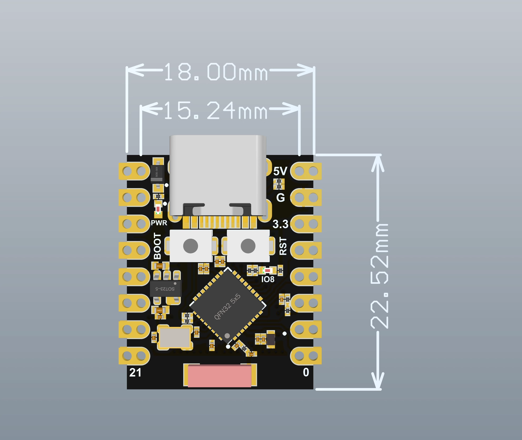
- Powerful CPU: ESP32-C3, 32-bit RISC-V single-core processor running at up to 160 MHzWiFi: 802.11b/g/n protocol, 2.4GhHz, support Station mode, SoftAP mode, SoftAP+Station mode, mixed modeBluetooth: Bluetooth 5.0Ultra-low power consumption: deep sleep power consumption is about 43μAAbundant board resources: 400KB SRAM, 384KB ROM built-in 4Mflash.Chip model: ESP32C3FN4Ultra-Small Size: As small as your thumb (22.52x18mm) Classic form factor for wearables and small projectsRobust Security Features: Cryptographic hardware accelerators supporting AES-128/256, hashing, RSA, HMAC, digital signatures and secure bootRich interfaces: 1xI2C, 1xSPI, 2xUART, 11xGPIO(PWM), 4xADCSingle-sided component, surface mount designOnboard LED blue light: GPIO8 pin
Pin diagram
 Ardunino ESP32C3 Dev Module Pin Mapping
size drawing
 Dimensions
Schematic
 schematic diagram
external power supply
If external power supply is required, just connect the + stage of the external power supply to the 5V position and GND to the negative pole. (support 3.3 ~ 6V power supply). Remember that when connecting to an external power supply, USB cannot be connected, and you can only choose between USB and external power supply.
Notice
When welding, please be careful not to short-circuit the positive and negative poles, which may burn the battery and equipment.
WIFIANTENNA
If you want to use an external antenna, you can connect an external antenna according to the picture below.

getting Started
Hardware settings
You need to prepare the following:
1 ESP32C3SuperMini
1 computer
1 x USB Type-C data cable
hint
Some USB cables can only provide power and cannot transfer data. If you don't have a USB cable or don't know if your USB cable can transfer data, you can buy a Type-c cableopen in new window
- Step 1. Connect ESP32C3SuperMini to computer via USB Type-C data cable

Software settings
- Step 1. Download and install the latest version of Arduino IDE according to your operating system
{{https://www.nologo.tech/assets/img/arduino/other/ArduinoIDE.png?nolink&}}open in new window
If the download is slow, you can download it in the domestic Arduino communityArduinoIDEDownload addressopen in new window
Step 2. Launch the Arduino application
Step 3. Add the ESP32 board package to the Arduino IDE
Navigate to File > Preferences and fill in the “Additional Boards Manager URL” with the following url:
https://raw.githubusercontent.com/espressif/arduino-esp32/gh-pages/package_esp32_index.json

Navigate to Tools > Board > Boards Manager…, enter the keyword “esp32” in the search box, select the latest version of esp32 and install it.

Navigate to Tools > Development Boards > ESP32 Arduino and select “ESP32C3 Dev Module”. The list of boards is a bit long and you need to scroll to the bottom to get to it.

Navigate to Tools > Ports and select the serial port name of the connected ESP32C3SuperMini. This is probably COM3 or higher (COM1 and COM2 are usually reserved for hardware serial ports).
flashing LED
Step 1. Copy the following code to Arduino IDE
''// define led according to pin diagram
int led = 8;

void setup() {
  // initialize digital pin led as an output
  pinMode(led, OUTPUT);
}

void loop() {
  digitalWrite(led, HIGH);   // turn the LED on
  delay(1000);   // wait for a second
  digitalWrite(led, LOW);    // turn the LED off
  delay(1000);               // wait for a second
}

''
Once uploaded, you will see the LED on the board blink with a 1 second delay between each blink.
评论
eius occaecati qui totam consequatur consequuntur quia sed non itaque. quos consectetur sint repellat voluptatem eaque ab voluptate distinctio deleniti accusantium beatae nisi dolore reiciendis cum. h
porro impedit ut qui voluptatem explicabo eum sint ut natus atque unde adipisci corrupti rerum. et hic corrupti fuga magnam non inventore dolorem. reiciendis quia neque quis hic quo iure unde dolor mo
reprehenderit eius voluptatibus tempora qui voluptatum quaerat similique mollitia qui repudiandae culpa. velit laudantium sed iure quod perspiciatis sit et voluptatem enim eos a et quo consequatur et
assumenda aut dolores ducimus expedita sunt vel laudantium ea non omnis expedita molestiae consequatur non ullam doloremque atque. eum sed nesciunt et nulla velit nam soluta corrupti omnis praesentium
dolor voluptatem perspiciatis repellat quos. architecto cumque aut labore assumenda explicabo esse nihil dolore velit.
<a href=https://cryptolake.online/crypto3>News on crypto adoption</a>
Can you send me the documentation of these hardware? ESP32-2424S012C-I
*Данная статья носит информационный характер и предназначена исключительно для ознакомительных целей.*